Field-Programmable, Chopper-Stabilized,
Unipolar Hall-Effect Switches
A3250 and
A3251
14
Allegro MicroSystems, Inc.
115 Northeast Cutoff, Box 15036
Worcester, Massachusetts 01615-0036 (508) 853-5000
www.allegromicro.com
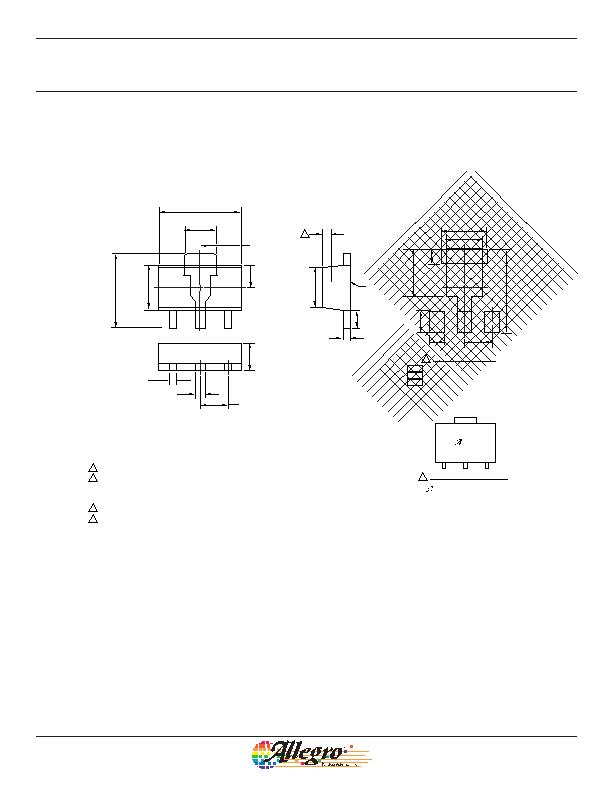
Package LT, 3-Pin SOT89
Parting
Line
2.24
1.14
3
2
1
A
A Active Area Depth, 0.78 mm REF
B
C
D
C
2X 1.50 BSC
4.50?.10
1.50?.10
0.50?.06
0.42?.06
1.73
+0.10
0.11
2.20
+0.09
0.07
2.45
+0.15
0.16
4.10
+0.15
0.16
1.00
+0.20
0.11
0.40
+0.04
0.05
Branding scale and appearance at supplier discretion
Hall element, not to scale
Reference land pattern layout (reference IPC7351 SOT89N);
All pads a minimum of 0.20 mm from all adjacent pads;
adjust as necessary to meet application process
requirements and PCB layout tolerances
Standard Branding Reference View
NNT
1
= Supplier emblem
N = Last two digits of device part number
T = Temperature code
For Reference Only; not for tooling use (reference JEDEC. TO-243AA)
Dimensions in millimeters
Dimensions exclusive of mold flash, gate burrs, and dambar protrusions
Exact case and lead configuration at supplier discretion within limits shown
1.50
1.00
0.80
2.60
2.00
2.50
0.70
4.60
B
PCB Layout Reference View
Basic pads for low-stress, not self-aligning
Additional pad for low-stress, self-aligning
Additional area for IPC reference layout
发布紧急采购,3分钟左右您将得到回复。
相关PDF资料
A3260LUA
IC SW HALL EFFECT BIPO 3-SIP
A3282LLHLT-T
IC SW HALL EFFECT CHOPPER SOT23W
A3340EUA-T
IC SW HALL EFFECT PREC 3-SIP
A3422LKA-T
IC SENSOR DIRECT/DETECT 5-SIP
AAH002-02
SENSORS MAGNETIC FIELD 8SOIC
AD221-00
SENS MAG SW 20G CROS AXIS 8-MSOP
ADH025-00
SENSOR MAG SW 10G CRS AXS 8-MSOP
ADL024-14E
DIGITAL SWITCH 55HZ ULLGA
相关代理商/技术参数
A3251LUATL
制造商:ALLEGRO 制造商全称:Allegro MicroSystems 功能描述:Field-Programmable, Chopper-Stabilized Unipolar Hall-Effect Switches
A325400284-200
制造商: 功能描述: 制造商:undefined 功能描述:
A32550-0009
功能描述:重负荷电源连接器 A32 SOCKET 50mm 50MMSKTCON RoHS:否 制造商:Hirose Connector 系列:PS2 产品类型:Connectors 位置/触点数量: 端接类型:Crimp 触点材料: 触点电镀:Gold 电压额定值: 电流额定值:300 A 附件类型:
A32550-0049
功能描述:重负荷电源连接器 A32 SOCKET 50mm WITH 2 AUX/2 PILOT CONT RoHS:否 制造商:Hirose Connector 系列:PS2 产品类型:Connectors 位置/触点数量: 端接类型:Crimp 触点材料: 触点电镀:Gold 电压额定值: 电流额定值:300 A 附件类型:
A32550-1009
功能描述:重负荷电源连接器 A32 SOCKET 50mm 50MMSKTCON RoHS:否 制造商:Hirose Connector 系列:PS2 产品类型:Connectors 位置/触点数量: 端接类型:Crimp 触点材料: 触点电镀:Gold 电压额定值: 电流额定值:300 A 附件类型:
A32550-1019
功能描述:重负荷电源连接器 A32 SOCKET 50mm WITH 2.5mm AUX CONT RoHS:否 制造商:Hirose Connector 系列:PS2 产品类型:Connectors 位置/触点数量: 端接类型:Crimp 触点材料: 触点电镀:Gold 电压额定值: 电流额定值:300 A 附件类型:
A32550-1049
功能描述:重负荷电源连接器 A32 SOCKET 50mm WITH 2 AUX/2 PILOT CONT RoHS:否 制造商:Hirose Connector 系列:PS2 产品类型:Connectors 位置/触点数量: 端接类型:Crimp 触点材料: 触点电镀:Gold 电压额定值: 电流额定值:300 A 附件类型:
A32570-0009
功能描述:重负荷电源连接器 A32 SOCKET 70mm 70MMSKTCON RoHS:否 制造商:Hirose Connector 系列:PS2 产品类型:Connectors 位置/触点数量: 端接类型:Crimp 触点材料: 触点电镀:Gold 电压额定值: 电流额定值:300 A 附件类型: